Automation of a Water Treatment System Using PLC and HMI
Introduction
A PLC program has been written to automate a water treatment system along with an HMI for users to control the system
Input / Output
Three Analog Inputs -
inlet pressure transducer - measure the water pressure before entering into the filter
outlet pressure transducer - measure the water pressure after passing the filter
Water level transmitter - measure the water level inside the tank
One Digital Input -
Flow switch - ON or OFF the flow of water from the main water supply
Seven Digital Outputs -
6 solenoid valves - control the direction of flow of water inside the pipes
1 pump - pump the water from the main water supply to the filter
Process
Forward Flow -
Water goes from main water supply to filter then the filtered water goes to the storage tank
Filter Wash Flow -
Clean the filter when the contaminant level inside the filter exceeds the threshold level
Forward Flow
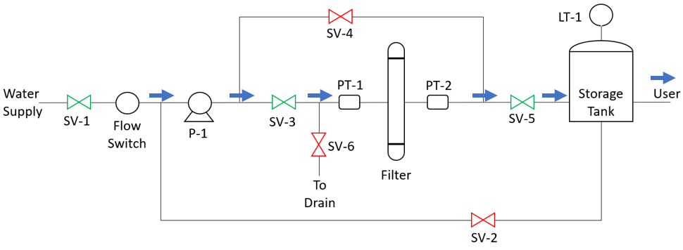
State of Digital I/O –
- Pump (P-1) ON
- Solenoid valves ON (SV-1, SV-3, SV-5)
- Solenoid valves Off (SV-2, SV-4, SV-6)
Conditions –
- When system is running
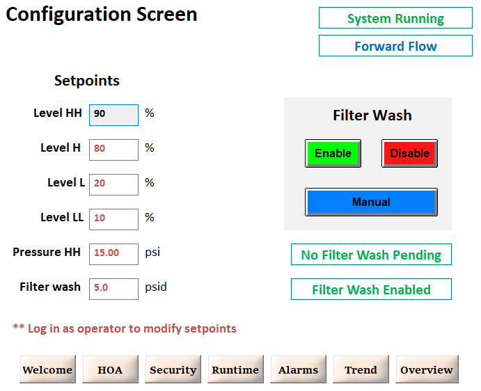
- Stops when water level LT-1 > 80%
- Starts when water level LT-1 < 20%
Filter Wash Flow
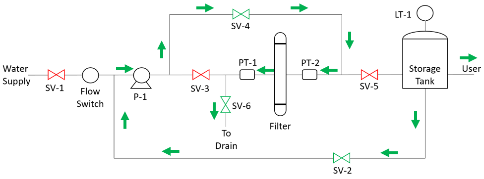
State of Digital I/O –
- Pump (P-1) ON
- Solenoid valves ON (SV-2, SV-4, SV-6)
- Solenoid valves Off (SV-1, SV-3, SV-5)
Conditions –
- When the inlet pressure is more than 5 psi then outlet pressure
- Starts when water level in the storage tank is more than 80%


