Ø Range: ±8 pF
Ø No. of capacitors: 6
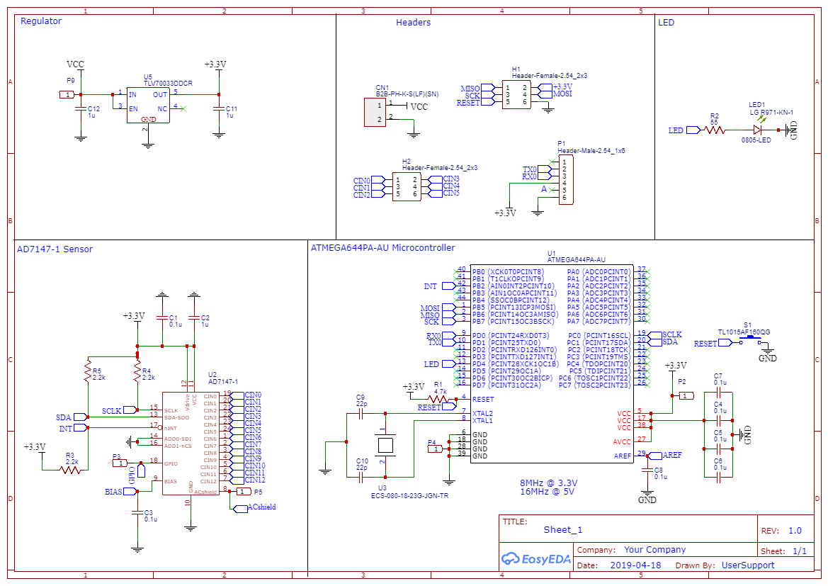
Ø Circuit was designed using the datasheet of AD7141
Ø Range: ±8 pF
Ø No. of capacitors: 6
- Circuit design guideline from the Analog Devices, Inc. can be found on the datasheet (Page no. 41)

- Our schematic diagram from EasyEDA


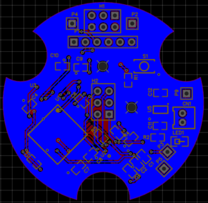
Top Layer

Bottom Layer
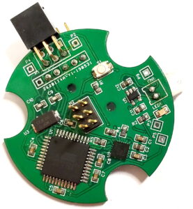
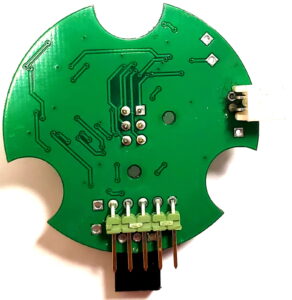
Ø PCB after assembly of all components (Images below)

Top Layer

Bottom Layer
Ø AD 7147-1 chip is used as capacitance to digit converter (CDC)
o 6 input channels are used among 13 channels
o Operating in full power mode
Ø ATMEGA644PA-AU microcontroller is used to collect data
o Collect digital data from CDC using I2C communication
o Send the digital data to the computer using serial communication
o Used Arduino.h for digital read and write
o Used Wire.h for I2C communication
Ø 2×3 male – female right angle connector for programming the microcontroller
Ø 2×3 male - male connector for connecting 6 capacitors
Ø Right-angle JST Battery connector
Ø 1×6 right-angle male - male connector sending digital capacitance data to the computer
ØThe code can be found in the following Github link -
https://github.com/shafiqur09me/Digital-Capacitance-Measurement