I did this work while working as a graduate research assistant at the Biorobotics and Biomechanical Lab at the University of Maine under Prof. Babak Hejrati. The purpose of this project was to develop a capacitive-based force sensor capable of directly measuring three-dimensional ground reaction forces (GRFs) during walking. Accurate measurement of 3D GRFs is essential for comprehensive gait analysis, as these forces provide critical insight into balance, propulsion, and stability during locomotion. Existing wearable systems typically measure only the vertical component and estimate the shear forces using predictive models. Also, non-wearable, traditional gait analysis tools like force platforms and instrumented treadmills are expensive and unsuitable for natural, overground walking. To overcome these limitations, this project aimed to develop a wearable 3D force sensor that enables reliable, real-time force measurement in both indoor and outdoor environments.
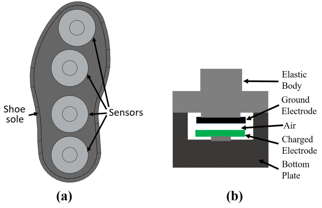
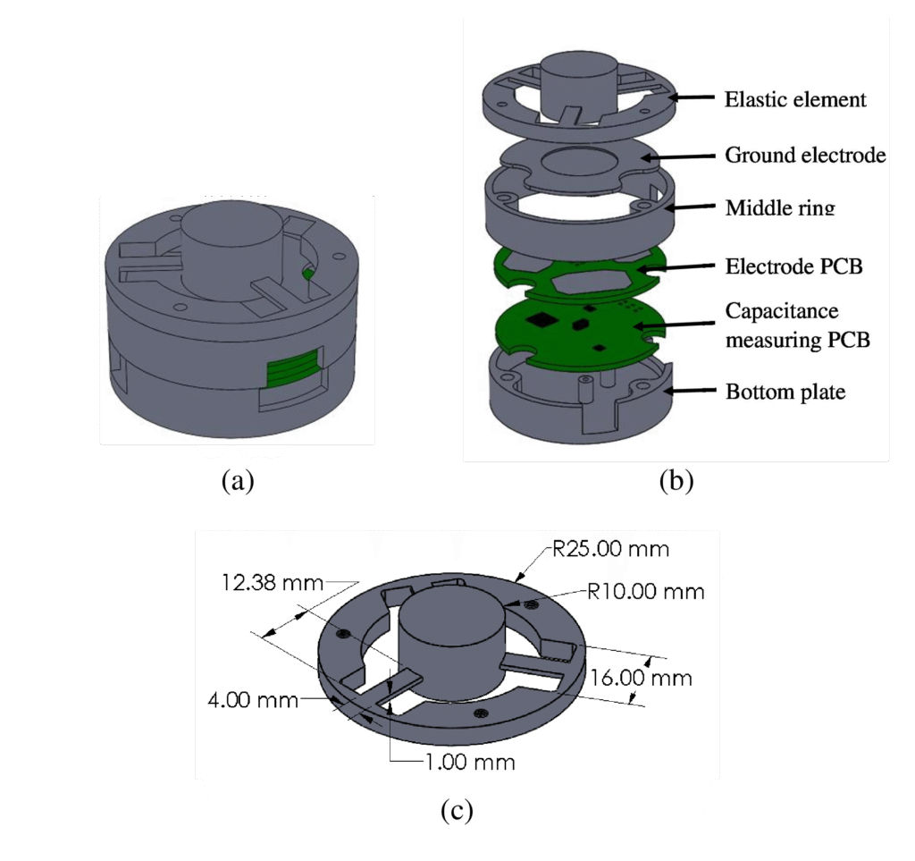
The initial design involved embedding four sensors inside the shoe sole. Each sensor includes an elastic body placed on top of a bottom plate. The capacitors consist of three on-board PCB-based electrode plates and one common ground electrode. The common ground electrode is attached to the elastic body and moves as the elastic body moves under load conditions. The electrode PCB sits fixed on the bottom plate.
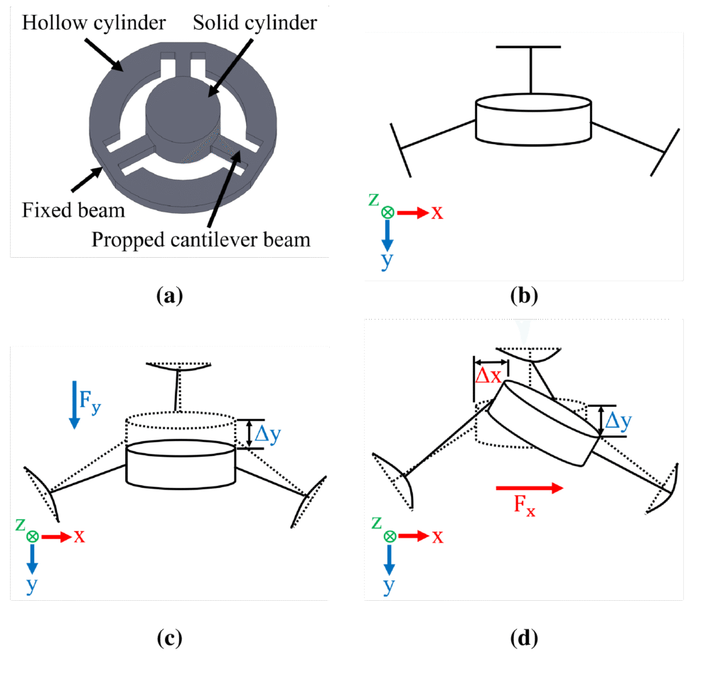
The elastic element consists of two cylinders. One is a hollow outer cylinder. The other is a solid inner cylinder. The inner cylinder is positioned concentrically inside the outer cylinder. The two cylinders are connected by three propped cantilever beams and three fixed beams. These beams allow controlled elastic deformation when force is applied.
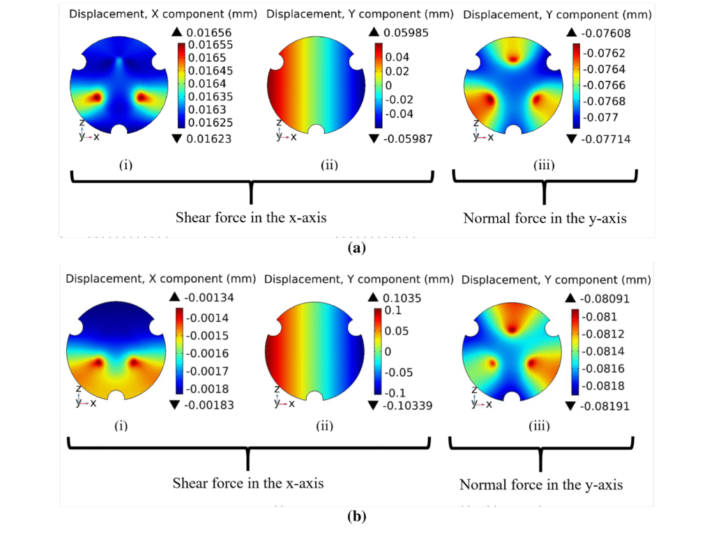
Structural analysis was performed in COMSOL Multiphysics to study the movement of the ground electrode under applied forces in different directions. I analyzed how the dimensions of the beams affect the movement of the ground electrode. The simulation results helped to refine the design of the elastic element.
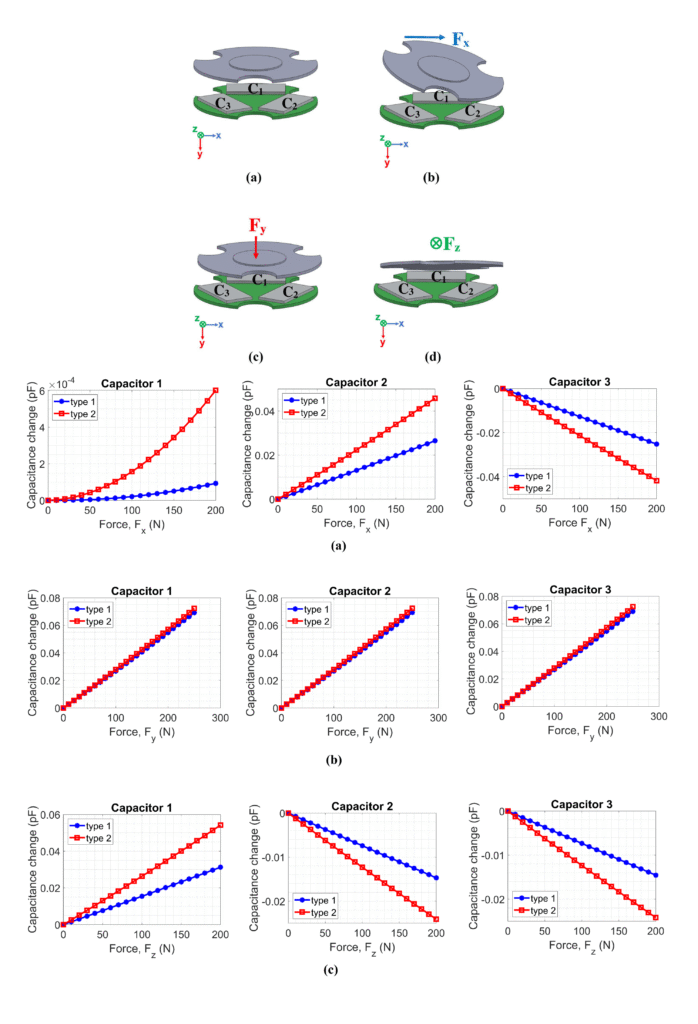
Later, electromechanical analysis was performed to verify the findings in the structural analysis.
Final dimensions of the elastic element were found manually based on the structural and electromechanical analysis. This process can be automated by using COMSOL’s LiveLink for SolidWorks and LiveLink for MATLAB.
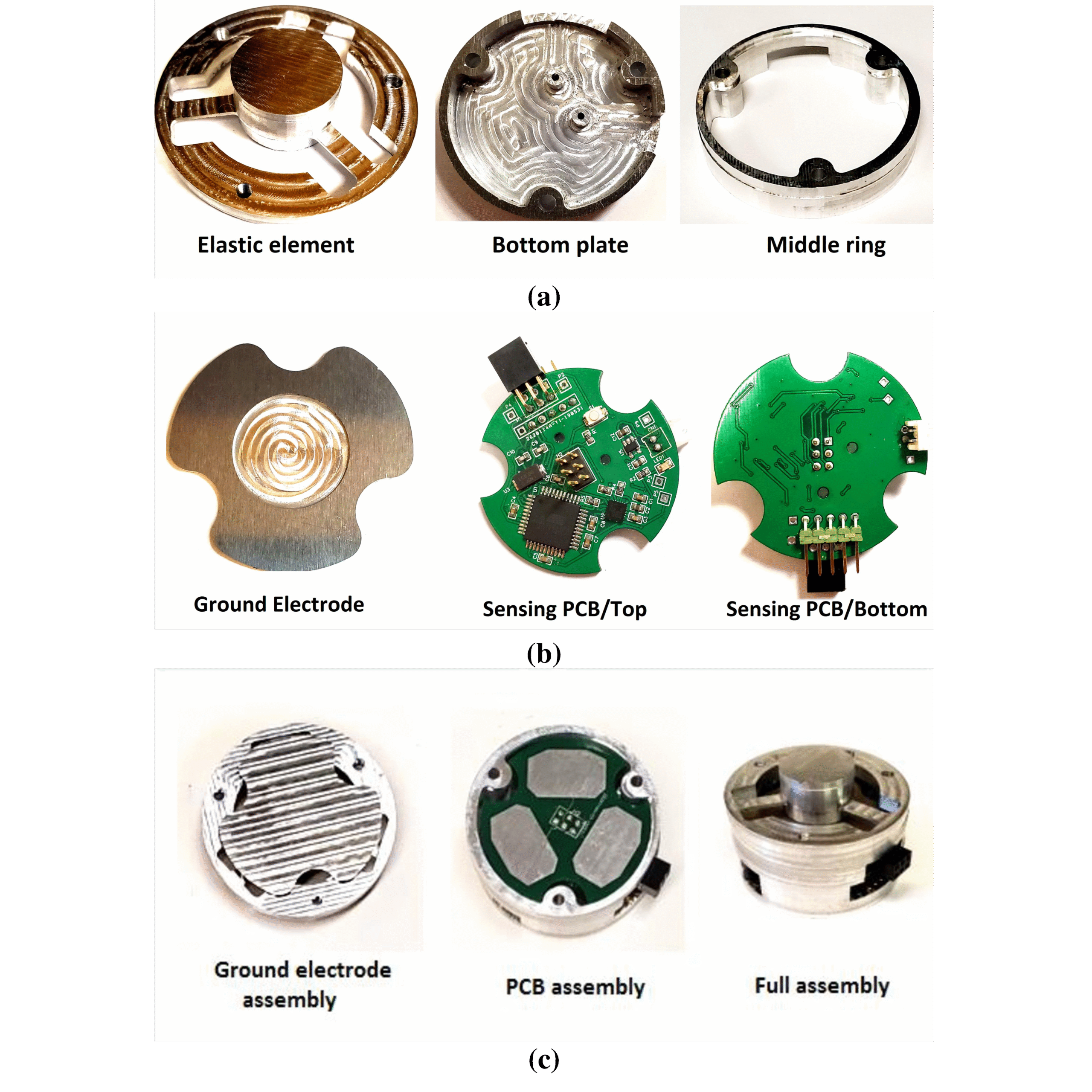
The two PCBs sit on top of the bottom plate. The middle ring surrounds the elastic element’s lower section, acting as a spacer and structural support between the bottom plate and the elastic element. The ground electrode is attached to the top of the elastic element, and the elastic element itself rests on the middle ring, allowing it to deform under applied forces while keeping it aligned in the housing.
The elastic body, ground electrode, middle ring, and bottom plate were made of Aluminum 7075-T6. The entire sensor fabrication process was done in-house, using a CNC machine (Bantam Tools Inc.) to machine all the parts. The G-Codes for the CNC machine were prepared in Autodesk® Fusion 360™.
The PCBs were designed using EasyEDA. The analog capacitance data was converted into digital data using a CDC 7147-1 chip. I programmed the microcontroller to collect the digital data from the CDC chip using I2C communication.
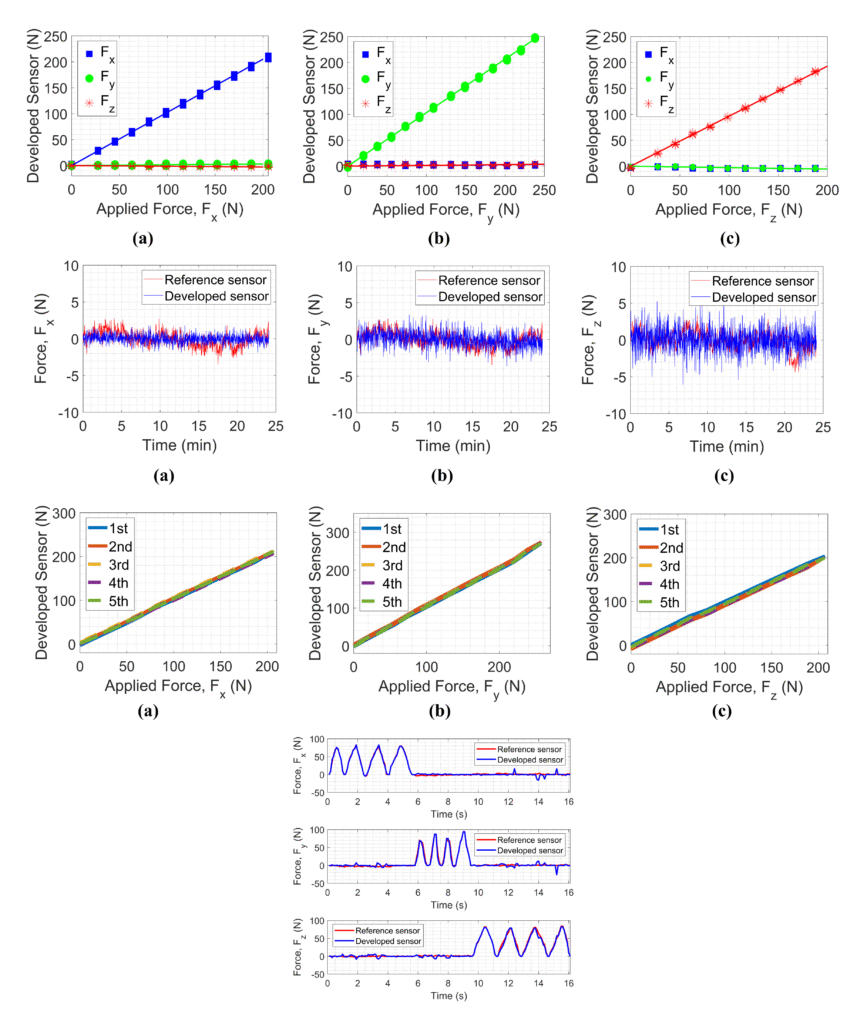
One experiment setup was designed using pulleys and weight blocks for calibration and evaluation of the developed sensor. A robotic manipulator was used to evaluate the dynamic response of the developed sensor.
Our experiments showed that the developed sensor achieves high accuracy, low cross-sensitivity (<2%), minimal drift, and excellent repeatability, with static and dynamic errors below 2.3% of full scale. These results confirm its potential as a low-cost, compact, and reliable solution for wearable gait analysis applications.